Mitigation systems
How a Radon Mitigation System Works
A useful system controls the pressure pathway below the building, then uses testing and monitoring to verify that the design is operating as intended.
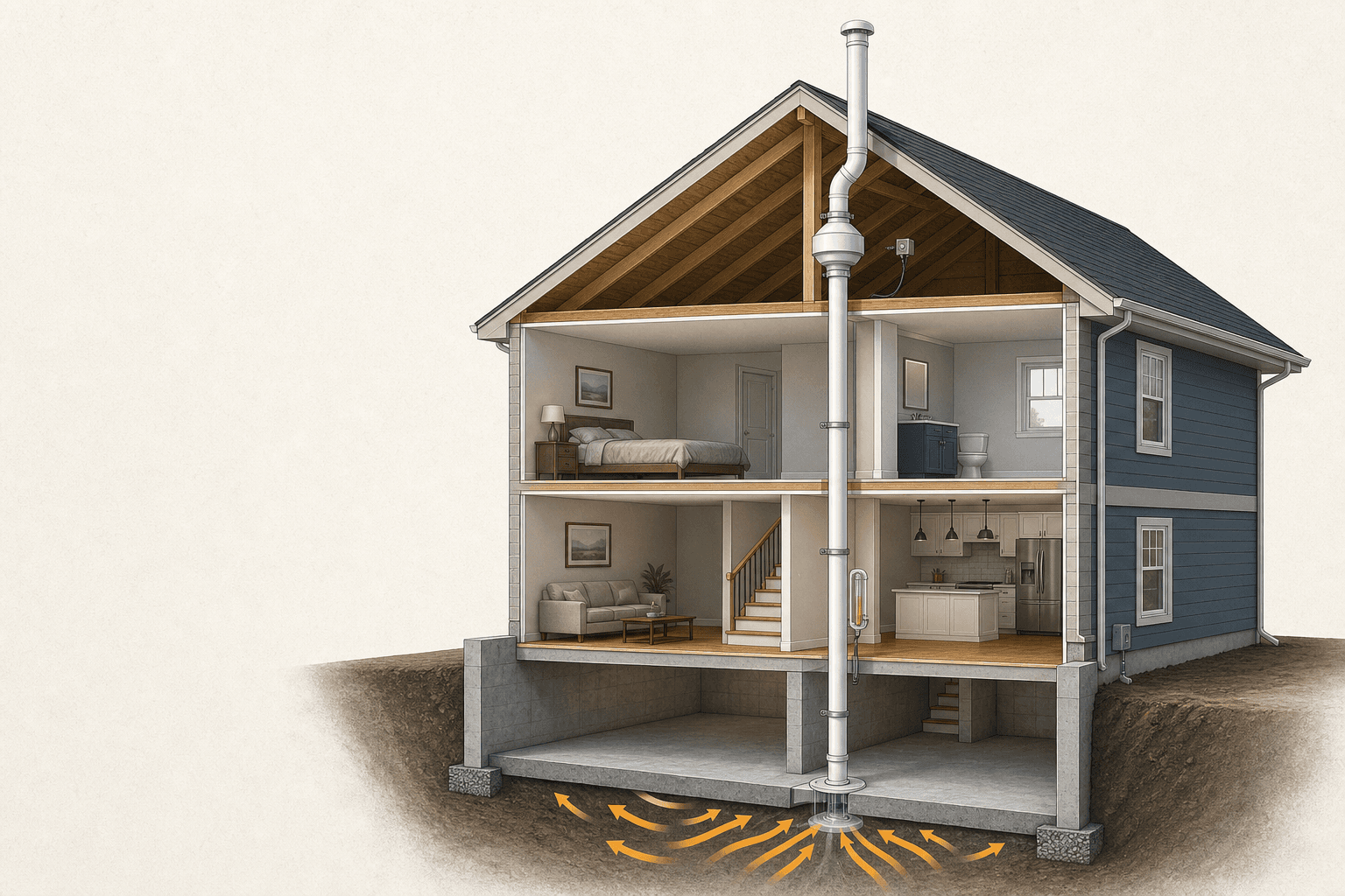
Illustration for explanation only. It is not a photograph of our work.
The central idea is pressure control
Soil gas can move through openings at slabs, foundations, sumps, drains, joints, and utilities. Active soil depressurization creates lower pressure below the home, giving that gas a controlled route to outdoor discharge before it enters occupied rooms.
The visible pipe is only one part of the design. Performance depends on whether suction reaches the needed sub-slab or sub-membrane area, whether the fan fits the airflow and pressure conditions, and whether the building has separate foundation zones.
Illustrative system overview. The actual design and component locations depend on the building and applicable standards.
Radon entry
Soil gas can move through foundation openings, joints, sumps, and utility penetrations.
Suction point
A connection through the slab or below a membrane opens a controlled collection path.
Pressure field
The fan creates lower pressure below the building so gas moves toward suction.
Crawlspace membrane
A durable sealed membrane can create the pressure boundary over exposed soil.
Fan
The selected fan maintains airflow and pressure for the actual system design.
Pipe route
Piping carries collected soil gas through a supported, serviceable route.
Discharge
The system releases gas outdoors at a location required by the applicable standard.
Verification
A warning device shows operating status. A radon test measures the indoor concentration.
Suction point and pressure field
A suction point connects the pipe to the space beneath a concrete slab or membrane. Material below the slab does not always allow air to move uniformly. Dense soil, interior footings, separate slabs, additions, and foundation transitions can interrupt communication.
That is why the highest test number does not reveal the number of suction points. Visual inspection, building knowledge, and diagnostic measurements inform the design.
Crawlspace membrane systems
For an earth-floor crawlspace, EPA consumer guidance describes sub-membrane suction. A high-density sheet covers the soil, is sealed at walls and penetrations, and is connected to a vent pipe and fan that draws soil gas from below the membrane.
A membrane is not simply loose plastic placed on the ground. Piers, irregular walls, utilities, water management, access, durability, and future service all influence the scope.
Fan, pipe, and discharge
The fan maintains the pressure difference that drives the system. Pipe sizing and route affect airflow, noise, condensate handling, appearance, weather exposure, and service access. Fan placement and discharge must follow the applicable standard and local requirements.
Interior routes can reduce weather exposure but may pass through closets, garages, or attic space. Exterior routes can reduce interior impact but add visible pipe and outdoor supports. A provider should explain the tradeoffs for the actual home.
The monitor is not a radon meter
Many active systems use a U-tube manometer or another warning device. It indicates pressure or operating status in the pipe. It does not report the radon concentration in the room.
Learn the system’s normal indication, check it regularly, and contact a qualified professional if the warning state changes, the fan becomes noisy, or a later radon test rises.
Post-installation proof
The system should be checked for proper operation, labelled, explained, and documented. Then a post-mitigation radon test measures initial effectiveness. EPA guidance recommends independent follow-up measurement to reduce potential conflict of interest.
Periodic retesting matters because fans and buildings change. Keep the system running as designed, inspect warning devices, retain records, and test after major building changes.